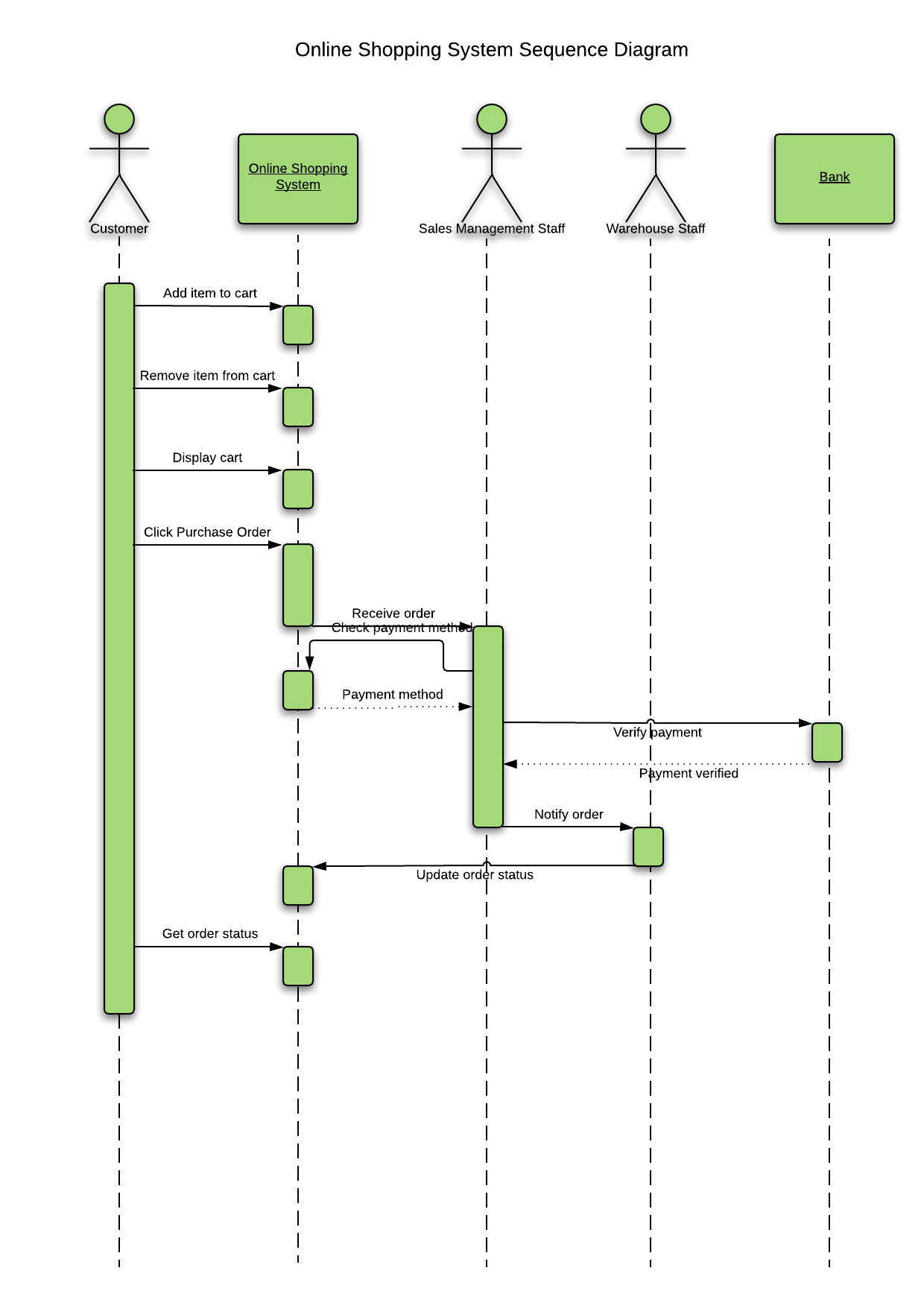

In the previous diagram, there are three execution occurrences. In the following diagram, the first message is a synchronous message (denoted by the solid arrowhead) complete with an implicit return message the second message is asynchronous (denoted by line arrowhead), and the third is the asynchronous return message (denoted by the dashed line).Ī thin rectangle running down the lifeline denotes the execution occurrence, or activation of a focus of control.

Messages can be complete, lost or found synchronous or asynchronous call or signal.

Boundary, control and entity elements from robustness diagrams can also own lifelines. This will usually be the case if the sequence diagram is owned by a use case. Sometimes a sequence diagram will have a lifeline with an actor element symbol at its head. If its name is "self", that indicates that the lifeline represents the classifier which owns the sequence diagram. A lifeline will usually have a rectangle containing its object name. Sequence diagrams are not intended for showing complex procedural logic.Ī lifeline represents an individual participant in a sequence diagram. Sequence diagrams are good at showing which objects communicate with which other objects and what messages trigger those communications. UML 2 Tutorial - Sequence Diagram Sequence DiagramsĪ sequence diagram is a form of interaction diagram which shows objects as lifelines running down the page, with their interactions over time represented as messages drawn as arrows from the source lifeline to the target lifeline.


 0 kommentar(er)
